Saturday, March 25, 2023

Construction of a CNC Machine


 Construction of a CNC Machine

Hello and welcome to all the tech lover's.

What if I ask you a question about your houses structure's, do you know how these structure's are made up? Many of you would answer in yes.

So let's learn about main components of a CNC machine 


Construction of CNC Machine 

The main parts of a CNC milling machine are the following.


Bed: 

It is the foundation of the machine and it provides a stable base for all other components. CNC machine's Bed is made of cast iron or steel and must be rigid and durable to withstand the forces and vibrations generated during machining. The size of the bed varies depending on the machine's capacity and application. For example, a small desktop CNC milling machine may have a bed size of 200 mm x 200 mm, while a large industrial machine may have a bed size of 3000 mm x 1500 mm or more.


Column: 

The column is a vertical structure that supports the spindle assembly and provides rigidity and stability to the machine. It is typically made of cast iron or steel and can range in height from a few hundred millimeters to several meters. The column's size and design depend on the machine's capacity, and it must be strong enough to support the spindle's weight and resist bending or twisting during machining.


Spindle assembly: 

The spindle assembly is the heart of the machine and rotates the cutting tool at high speeds to remove material from the workpiece. The spindle motor's power and speed depend on the machine's capacity and application, but typical values range from 3 kW to 30 kW and 6,000 to 24,000 rpm. The bearings used in the spindle assembly are typically high-precision angular contact ball bearings or tapered roller bearings, designed to provide low friction, high stiffness, and long life.


Tool changer: 

The tool changer is a critical component of a CNC milling machine, enabling automatic tool changes during the machining process. The tool changer's capacity and speed depend on the machine's design and application. For example, a small desktop machine may have a tool changer capacity of 6 to 10 tools, while a large industrial machine may have a capacity of 40 or more. The tool changer's speed and reliability are also essential, as tool changes must be fast and accurate to minimize machine downtime and maximize productivity.


Control panel: 

The control panel is where the operator inputs the commands for the machine to execute. It typically includes a computer, keyboard, and screen, along with specialized software for programming and controlling the machine. The software may be proprietary or open-source, depending on the machine's manufacturer and application. The control panel's design and interface are critical to the machine's usability and efficiency, and modern CNC machines often feature intuitive touchscreen interfaces and advanced programming features.


Worktable: 

The worktable is where the workpiece is mounted for machining. It can move along the X, Y, and Z axes to enable precise cutting of the material. The worktable's size and capacity depend on the machine's application and design, with some machines featuring multiple worktables or rotary tables for added flexibility. The worktable's precision and repeatability are critical to the machine's performance, with typical positioning accuracy of 0.01 mm or better.


Linear guides: 

Linear guides provide precise linear motion of the machine components along the X, Y, and Z axes. They ensure accuracy and repeatability of the machining process and are critical to them machine's performance. Linear guides typically use recirculating ball or roller bearings, with typical positioning accuracy of 0.005 mm or better.


Coolant system: 

The coolant system is responsible for cooling and lubricating the cutting tool and workpiece during machining. It also helps to flush away the chips and debris generated during the cutting process. The coolant system's design and capacity depend on the machine's application, with some machines featuring high-pressure coolant systems for improved chip evacuation and cooling. The coolant system's effectiveness is critical to the machine's performance, with insufficient cooling or lubrication leading to tool wear, workpiece damage.

The power supply:

is a critical component of a CNC milling machine, as it provides the electrical power needed to operate the machine's various components. The power supply must be designed to supply clean, stable power at the correct voltage and current levels required by the machine.


The power supply typically consists of several components, including transformers, relays, and other electrical components. The incoming power is typically supplied at 220-240VAC single-phase or 380-480VAC three-phase, depending on the machine's power requirements.


The power supply must be sized appropriately for the machine's capacity and application. The power requirements of a CNC milling machine depend on several factors, including the spindle motor's power, the size of the machine's linear motors, and the power consumption of other components such as the coolant system and control panel. As a result, the power supply's capacity can vary widely, with some small desktop machines requiring as little as 500W, while large industrial machines can require 20kW or more.


The power supply must also be designed to provide clean, stable power to the machine's components. Electrical noise, voltage spikes, and other power quality issues can cause problems with the machine's operation, leading to reduced accuracy, increased wear and tear, and other issues. To minimize these issues, the power supply may include components such as filters, surge protectors, and voltage regulators to ensure stable, clean power is supplied to the machine.

Sunday, March 5, 2023

Springs, What are Springs Their Types and Applications


What are Springs?


What are springs


Hello and welcome to another blog. I hope that you all are doing great and doing a great service for your industry.

Without any further delay let's continue our today's topic that I have been requested by one of my students about "Springs".

    Every one of us has played with toys in our childhood, and most of these toys were based on spring action. But we have never noticed that these springs are not just meant for toys their applications are far more in our daily routines whether it's a small pen you are writing with or it is a shock absorber from your vehicle or motorcycle, springs are everywhere.
Today we are going to introduce you to  some basic types of springs and their applications
Let's get ready and dive into the world of Springs.

Introduction

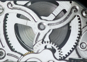
Springs are used in a wide range of devices, from a simple hand watch to large industrial machinery. Take apart any mechanism, and you'll almost certainly discover a spring in it. Springs are basically mechanical energy storage devices, similar to electrical storage batteries. they store energy when the load is applied and when the load is removed they release energy.

spring in a watch


Springs were used in clocks in approximately 1400s, and still they are used in today's modern technology. 

So here are some basic types of springs and their applications that everyone should be aware of: 

1- Helical Compression springs:-


Types of springs
 
   Compression springs are the most common type of spring used in everyday applications. These springs are designed to resist compressive forces and return to their original shape when the force is removed. They are used in various applications such as automotive suspensions, shock absorbers, and industrial machinery to absorb shocks and vibrations.

2- Helical Tension Spring:-

types of springs

    Tension springs are designed to resist tensile forces and are stretched to provide a force. These springs are used in many applications, such as screen doors, trampolines, and exercise equipment, to provide tension and support.

3- Helical Torsion Spring:-

types of springs


types of springs

    These are commonly used in many household items such as garage doors, clothespins, and mousetraps to provide rotational force. They are also used in clocks, watches, and other timepieces to provide precise movement.


4- Belleivlle Springs or Washers

types of springs

    
To give a high load capacity in a short space, they are utilised in various domestic appliances like dishwashers, washing machines, and faucets. Moreover, they are utilised in industrial pumps, valves, and machines.

5- Volute or Conical Springs

types of springs
    Volute or conical springs are a sort of cone-shaped spring. They are formed of coiled wire in the shape of a cone. The spring's diameter progressively expands from one end to the other. Because of its design, the spring may give a variable spring rate, which can be utilised to absorb shocks and vibrations in a variety of applications.

Volute springs are extensively used in automobiles and other vehicles to absorb shocks and vibrations caused by bumps or uneven terrain. They are also used in furniture, such as couches and chairs, to offer to cushion and support.


6- Leaf Springs

types of springs

types of springs

  
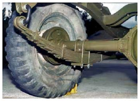
  A leaf spring is a type of spring that is made up of multiple thin, flat metal strips or "leaves" that are bolted together and placed on top of each other. The leaves are slightly bent, and the entire assembly is linked to the vehicle frame on one end and the axle on the other.

When the car encounters a bump or rough piece of road, the leaf spring contracts and absorbs the shock before returning to its former shape once the bump has gone. Leaf springs are extensively used in truck, bus, and other large vehicle suspension systems.


Saturday, February 25, 2023

Different Types of CNC Machines?


CNC (Computer Numerical Control) machines are advanced manufacturing tools that use computer software to control the movement and different operations such as cutting, drilling, and shaping of different materials. 

Looking for information about CNC Machines???? Then you are at the right place.
In today's topic, we are going to discuss Different types of CNC machines that are used in different industries to increase production and produce accurate parts.

CNC machines can be programmed to manufacture parts with high precision, accuracy, and consistency. This makes them ideal for the mass production of complex components. CNC Machines are widely used in various industries where high levels of precision and accuracy are required.


Some of the benefits of using CNC machines include:

  1. Increased productivity and efficiency
  2. Reduced labor costs
  3. Improved accuracy and consistency
  4. Ability to produce complex shapes and designs
  5. Faster turnaround times
  6. Reduced material waste
  7. Improved safety for operators.

Overall, CNC machines have revolutionized the manufacturing industry by making it possible to produce highly precise and complex parts at a much faster rate than traditional manufacturing methods.

So let's dive into the World of CNC with me

Different Types of CNC  Machines

1- CNC Lathe:

operator standing near a CNC lathe

1- An Operator Working on CNC Lathe

    CNC lathe is a type of machine tool that is used for shaping and machining cylindrical material. In lathe machine work piece is held in a device called a chuck and rotated. then a single point cutting tool removes the material from the workpiece bringing it to desired shape and size. All of these movements of cutter and workpiece are controlled by a computer programme, which ensures that the desired shape and dimensions are achieved with high accuracy and precision.

CNC lathes can be programmed for a variety of operations, including turning, facing, drilling, threading, and more. They are commonly used in the manufacturing industry to create complex parts for a variety of applications, such as automotive, aerospace, and medical devices.

One of the main advantages of using a CNC lathe is that it allows for faster and more efficient machining than traditional manual lathes. It also offers greater precision and repeatability, which is important for producing high-quality parts at scale. Overall, CNC lathes are an essential tool for modern manufacturing processes.

2- CNC Milling
CNC milling machine
2- A CNC Milling Machine

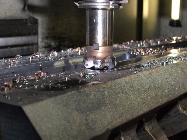
    CNC Milling machine uses a rotating cutting tool to remove material from the surface of the workpiece. The cutting tool is held in a spindle that can move along multiple axes to create complex shapes and features in the workpiece. The machine is controlled by a computer program that specifies the tool path and cutting parameters. CNC milling machines are used in a wide range of industries, from aerospace and automotive to electronics and medical device manufacturing. They are highly accurate and can produce complex shapes and features with a high degree of repeatability. CNC milling machines are essential tools for modern manufacturing, allowing for the efficient and precise production of parts and components.


3- CNC Cutter Grinder


Cutter being grinnded in cutter grinder

3- An Overview of CNC Cutter Grinder


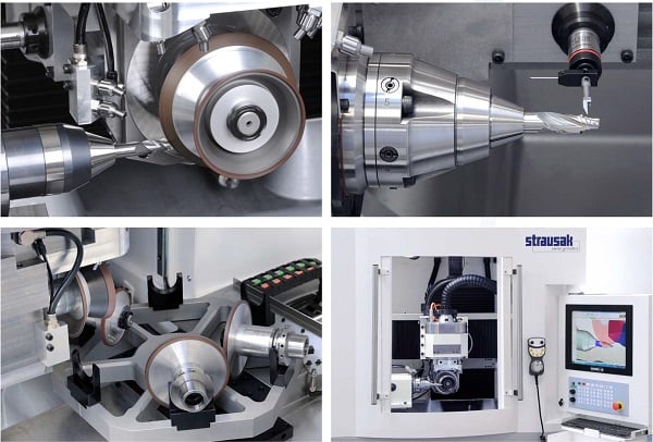
    CNC cutter grinder machine is a specialized tool used in the manufacturing industry to sharpen and reshape cutting tools such as end mills, drills, and step drills. It uses computer numerical control (CNC) technology to automate the grinding process, improving accuracy and consistency while reducing operator error. 

The machine typically consists of a rotating grinding wheel and a programmable control system that allows the user to input precise specifications for the tool's shape and size. The machine can grind tools to within a few microns of accuracy, allowing for precise and repeatable cuts. CNC cutter grinders are widely used in various industries, including aerospace, automotive, and medical device manufacturing, where precision cutting tools are essential for creating high-quality products.


4- CNC Plasma Cutter


cnc plasma cutter
4-A CNC Plasma Cutter in Action

    CNC plasma cutter is a type of computer-controlled machine that uses a high-velocity jet of ionized gas to cut through metal. The machine includes a plasma torch that generates an electrical arc between an electrode and the metal being cut. This arc ionizes the gas, which in turn heats up and melts the metal, allowing the plasma stream to cut through it with great precision. The CNC plasma cutter is capable of cutting through a wide range of metals, including steel, aluminum, and stainless steel, with thicknesses up to several inches. The machine is controlled by a computer that directs the plasma torch along the cutting path, allowing for intricate and precise cuts. The CNC plasma cutter is commonly used in industries such as metal fabrication, automotive repair, and construction.


5- CNC Wood Router


5- A CNC Wood Router

     CNC Wood Router is a computer-controlled cutting machine that uses a spinning router bit to cut and shape wood. It operates on three axes - X, Y, and Z - allowing it to create intricate 2D and 3D designs with high precision and accuracy. The machine receives its instructions from a computer-aided design (CAD) program, which is loaded into the machine's control panel. The CNC Wood Router can be used to produce a wide range of wood products, including furniture, cabinetry, musical instruments, and decorative items. Its high-speed cutting capabilities and automated operation make it an efficient and cost-effective tool for woodworkers and manufacturers alike. CNC Wood Routers come in a range of sizes and configurations, allowing users to choose the machine that best fits their specific needs and budget.


6- CNC Laser cutter


6- CNC Laser Cutter in Action

    CNC laser cutter is a machine that uses a high-powered laser beam to cut and engrave a wide range of materials such as metal, plastic, wood, and more. The laser beam is focused on the material, creating a high-energy density point that melts, vaporizes, or burns away the material. The machine is controlled by a computer, which ensures that the laser cuts or engraves the design with high precision and accuracy. CNC laser cutters can be used for a variety of applications, such as creating intricate designs, customizing products, and producing prototypes. They are highly efficient and produce clean cuts, minimizing waste and reducing production time. CNC laser cutters have become a popular choice in many industries due to their versatility, accuracy, and efficiency.


7- CNC Pipe Bending

7- A Pipe Bending Machine 


    CNC Pipe Bending machine is a specialized type of CNC machine used to bend metal pipes and tubes into specific shapes and angles. It operates using a computer-controlled system that controls the machine's movements, allowing for precise and accurate bending of pipes to meet the required specifications. The machine uses mandrels and clamps to hold the pipe in place and then applies pressure to bend the pipe into the desired shape. CNC Pipe Bending machines are commonly used in industries like automotive, aerospace, and construction, where pipes and tubes of various shapes and sizes are needed for different applications. They offer increased efficiency, accuracy, and repeatability in the bending process, resulting in reduced waste and cost savings for the manufacturer.

8- CNC EDM
8- An EDM

    CNC EDM (Electrical Discharge Machining) machine is a type of computer-controlled machine that uses electrical discharges to remove material from a workpiece. The machine consists of an electrode and a workpiece, both immersed in a dielectric fluid. An electrical discharge is generated between the electrode and the workpiece, which erodes the workpiece material, creating the desired shape. The electrode is moved along the workpiece's surface according to a computer program, which specifies the shape and depth of the cut. CNC EDM machines are commonly used for shaping and drilling hard materials, such as metals, ceramics, and composites. They offer high precision and accuracy, making them suitable for manufacturing complex and intricate parts. Additionally, CNC EDM machines are capable of producing a fine surface finish and can work with materials that are difficult or impossible to machine with conventional methods.


9- CNC Water jet


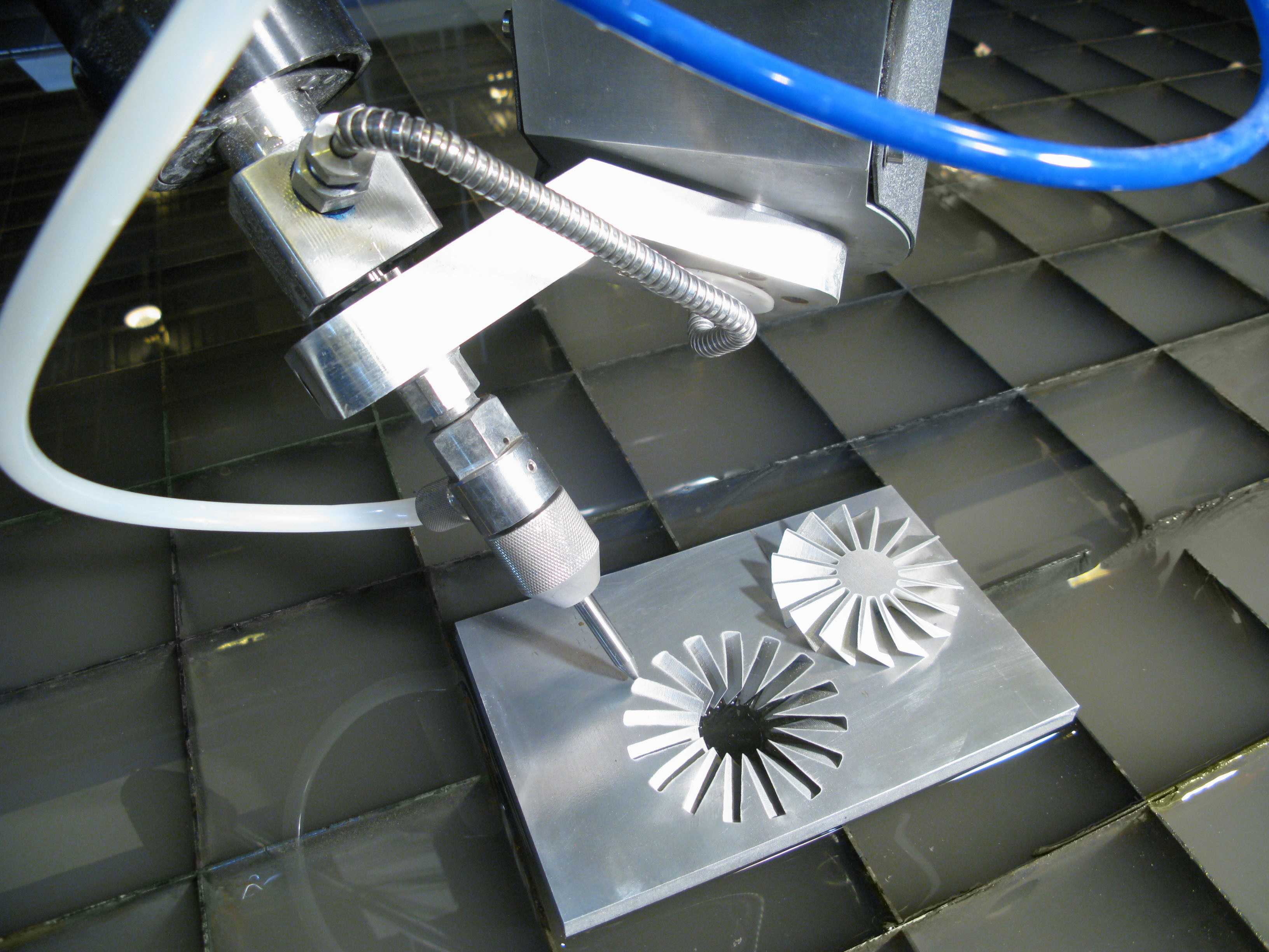
9- Water Jet Cutting Metal
(http://www.wardjet.com/copyright.aspCC BY-SA 3.0, via Wikimedia Commons)

    CNC water jet machine is a type of cutting tool that uses high-pressure water mixed with an abrasive material to cut through a variety of materials including metal, stone, and glass. The machine is controlled by a computer program, which directs the water jet to cut the material to the desired shape and size with high precision. This process is non-thermal and does not produce heat-affected zones, which makes it ideal for materials that are sensitive to heat, such as plastic and foam. The machine is capable of cutting materials up to 6 inches thick and can create intricate designs with high accuracy. CNC water jet machines are commonly used in industries such as aerospace, automotive, and architecture for cutting and shaping a wide range of materials.


Photo Credits:
1- Somesomething243CC BY-SA 4.0, via Wikimedia Co
2-  Handtmann01CC BY-SA 3.0, via Wikimedia Commons
3-  https://www.sme.org/


Difference between Lever and Co-Axial Dial Indicator


 Key Differences and Applications

Hello and welcome to another exciting day. Hope that all of you engineers and technicians are doing their best to meet the demands of today's market.

Everyone of use to take some kind of measurement everyday, it can be measuring distance to your college or workplace or it can be measuring weight of groceries that your wife asks to purchase 😉😉😉🥳🥳.

But in case of manufacturing technology when it comes to measurements, there is no chance of mistakes. We use different instrument to take measurements which includes Vernier caliper, Micrometers, Gauges and Dial Indicators.

Today's topic is about 2 common types of dial indicators. 

Introduction:

Mechanical measuring instruments are crucial tools in various industries, providing accurate measurements and quality control. 


Two commonly used dial imdicators are the lever dial indicator and coaxial dial indicator. In this article, we will explore the key differences between these two instruments and their respective applications.


What is a Lever Dial Indicator?

Lever dial indicators are designed with a lever arm, a fixed pivot point, and a graduated dial that displays the readings. Leaver Dial indicators are ideal for measuring following:

1- Deviations in different profiles

2- Taking center point of hole.

3- Measuring center distance of holes.

4- Checking alignment.

5- Measuring flatness. 


What is a Coaxial Dial Indicator?

Coaxial dial indicators have a central spindle, a rotating lever arm around the spindle, and a graduated dial that displays the readings. 

These are more sensitive than lever dial indicators and are ideal for measuring runout, concentricity, and alignment in cylindrical parts.


Design Differences: Lever Dial vs Coaxial Dial Indicator

Lever dial indicators have a horizontal and vertical orientation and measure deviations in two directions.

Coaxial dial indicators are used to measure runout, concentricity, and alignment in cylindrical parts and have a perpendicular orientation.


Sensitivity Differences: Lever Dial vs Coaxial Dial Indicator

Coaxial dial indicators are more sensitive than lever dial indicators, making them ideal for measuring small deviations in dimensions or positioning.


Range of Measurement Differences: Lever Dial vs Coaxial Dial Indicator

Lever dial indicators have a larger range of measurement than coaxial dial indicators, making them useful for measuring larger deviations in dimensions or positioning.


Applications of Lever Dial Indicator

Lever dial indicators are commonly used in manufacturing and engineering applications to measure deviations in linear dimensions or positioning.


Applications of Coaxial Dial Indicator

Coaxial dial indicators are ideal for use in the manufacturing and engineering of rotating components, where they can measure runout, concentricity, and alignment in cylindrical parts.


Conclusion

The choice between a lever dial indicator and a coaxial dial indicator depends on the specific application's requirements and the level of precision needed. Lever dial indicators are more suitable for larger deviations, while coaxial dial indicators are better for smaller deviations and cylindrical parts. By understanding the key differences between these two instruments, you can choose the most suitable one for your needs.


Thursday, February 23, 2023

Introduction to Automation


Introduction to Automation

Have you ever wondered that the phone that you are using right now , is made up of hundreds of parts combined together,,, yesses that’s true. Cars, Trains and planes are also made up of hundreds of thousands parts combined together, and these all parts work together to fulfill your needs.

 But have you ever wondered how theses all small parts are manufactured and create a product that you and I use in our every day life to fulfill our needs.

Lets dive together into the world of Production Systems,,

Production system can be defined as collection of man, machines, materials and different methods organized in such a way to achieve the manufacturing targets of an organization.

Lets divide productions systems into 2 categories

1- Support systems

2- Facilities

Support systems mainly consist of the different methods including products designs, ordering materials, dispatching it to the required stations, removing different technological and logistical problems and also ensuring that the product meets the desired standards.

Facilities are the all the systems that are required to shape a product into reality, including the building of the factory, machines and all the other equipment used at different levels during the manufacturing of the product.

        In early days of the industrial revolution most these tasks were done manually, but it was a laborious process and there were many deficiencies with this process. with the advancements of the technology these tasks were gradually shifted to be performed automatically it increased the efficiency and the productivity of the factory.


ChristophRoser. Photo credit "Christoph Roser at AllAboutLean.com".CC BY-SA 4.0, via Wikimedia Commons

        In todays world many of these processes are automated means there are computerized systems who are performing these tasks for us. The most famous example of these automated systems are the self driving vehicles, in which there is very little effort of the operator is required to complete the task and it take us to our destination.

Benefits of Production Automation

Production automation offers many benefits, including:

     1  Increased efficiency            2- Improved safety

     3 Productivity                         4- Quality

     5 Reduced labor costs

By automating tasks, manufacturing plants can produce more products in less time while maintaining consistent quality. This can result in increased profitability and a competitive advantage in the market.

Examples of Production Automation

         1-  Automotive

The automotive industry is one of the largest users of production automation. Robots are used extensively in the assembly line to perform tasks such as welding, painting, and assembly of parts.

 For example, robots can weld car bodies with high precision and speed, resulting in consistent quality and faster production cycles  

2-  Food Processing Industry

The food processing industry is another industry that extensively uses production automation. Automated systems are used for tasks such as sorting, cleaning, cutting, and packaging of food products.

For example, in a fruit processing plant, automated systems can sort fruits based on their size and color, remove any defects, and cut them into the desired shape. These systems can also package the fruits into containers or bags and label them with barcodes for tracking. 

3-    Aerospace Industry

The aerospace industry uses production automation for tasks such as machining, assembly, and testing of aircraft components. For example, in the manufacturing of aircraft engines, automated systems can perform tasks such as drilling, milling, and grinding with high precision and speed, resulting in consistent quality and faster production cycles.

Automated systems can also be used for assembly tasks, such as joining components with adhesives or fasteners. These systems can perform tasks that are difficult or impossible for human workers, such as joining components in tight spaces or at awkward angles.

                 4-    Electronics Industry

The electronics industry extensively uses production automation for tasks such as assembly, testing, and inspection of electronic components and devices. For example, in the manufacturing of printed circuit boards (PCBs), automated systems can apply solder paste, place components, and perform reflow soldering with high precision and speed.

Automated systems can also be used for testing and inspection of electronic components and devices. For example, in the manufacturing of smartphones, automated systems can perform tests such as checking the touch screen, camera, and battery performance, ensuring that each device meets the required standards.

Conclusion

    In conclusion, production automation is a crucial aspect of modern manufacturing that offers many benefits. Examples of production automation include robots, automated material handling systems, conveyor belts, computer-controlled machines, and quality control systems. By embracing production automation, manufacturing plants can increase efficiency, productivity, and quality while reducing labor costs and improving safety.

Monday, February 20, 2023

How does CNC Machining works?

        CNC machines are transforming the manufacturing and fabrication sectors by enabling for the accurate and economical manufacture of complex parts and components. CNC machines have altered the way we create, design, and construct, from carpentry and metalworking to 3D printing and beyond. In this article, we'll look at CNC machines and their various uses, as well as their promise for the future of manufacturing. Whether you're a professional in the field, a hobbyist, or simply inquisitive about the world of CNC, there's something for you here. Now, let's get started and discover the fascinating world of CNC machines!

How CNC Machining works?

CNC machining begins with the development of a 3D computer model of the object or product to be manufactured. This model is built with computer-aided design (CAD) software and displays the part in detail, including its size, form, and specs.

1. Women working on CAD Model

When the 3D model is finished, the CAD software is used to build a programme that controls the CNC machine's motions. This script, known as the G-code and M-code, offers a collection of instructions that direct the machine how to move, where to cut, and how fast to work.

2. CAD/CAM Process 

        The G&M-code programming is put into the CNC machine, and the material to be machined is loaded onto the worktable. The machine is then set up, and the cutting tools are loaded into it. After everything is in position, the machine is started, and the cutting tools begin to move, cutting away at the material according to the instructions specified in the G&M-code programming.

3. Machining in Progress

The machine continues to cut away at the material until the part or component is finished. The final product is then taken from the machine and examined to ensure that it fits the appropriate requirements.


Photo Credits:

  1. <a href="https://www.freepik.com/free-photo/young-remote-woman-architect-working-modern-cad-program-overtime-industrial-female-engineer-studying-prototype-idea-personal-computer-showing-cad-software-device-display_18116160.htm#query=cad%20models&position=3&from_view=search&track=ais">Image by DCStudio</a> on Freepik
  2. Tebis Technische Informationssysteme AGCNCFräser at de.wikipedia, CC BY-SA 3.0 DE <https://creativecommons.org/licenses/by-sa/3.0/de/deed.en>, via Wikimedia Commons
  3. https://www.publicdomainpictures.net/pictures/150000/nahled/zerspanen-von-metall-1453645540oUd.jpg

CNC Machining, An Introduction for beginners.

    CNC machining uses computer-controlled machines to produce precise, complex, and accurate parts and components. These machines are controlled by a computer program to cut carry out different processes.

    CNC machines are used to cut and shape materials, producing parts with tight tolerances and intricate shapes. They are used in industries that require precision and accuracy. CNC machines are machines that can operate in three or more axes simultaneously, allowing them to produce complex shapes and contours accurately. They come in various types for example lathe, milling, routers, grinders and are equipped with tools such as cutting tools, drills etc.

1. A CNC Milling Machine

    CNC machining involves several steps, including designing the part, creating the required process programs, transferring the program to the CNC machine, and cutting and shaping the material to the required shape and size.


2. CAD/CAM Process 

            When speaking to the advantages of CNC machining there is one of the main advantage of CNC machining is the ability to produce high-quality parts consistently and quickly. CNC machines can work continuously without breaks, and they can produce parts in large quantities with minimal human intervention. This makes them ideal for mass production of parts and components.

    In conclusion, CNC machining is one of the most efficient and precise manufacturing techniques. It offers many advantages over traditional manual fabrication techniques in terms of efficiency and precision. A variety of industries use this type of technology, and with the rapid development of technology, the use of this technology is only expected to increase.


Photo Credits:

  1. HafeezJD, CC BY-SA 4.0 <https://creativecommons.org/licenses/by-sa/4.0>, via Wikimedia Commons
  2. Tebis Technische Informationssysteme AGCNCFräser at de.wikipedia, CC BY-SA 3.0 DE <https://creativecommons.org/licenses/by-sa/3.0/de/deed.en>, via Wikimedia Commons

Saturday, February 18, 2023

What is GD&T?


 Geometrical Dimensioning & Tolerancing

Hello and welcome to another exciting day. Hope that all of you are doing their best to meet the demands of today's industrial market.

Today's topic is all about GD & T.

So let's dig deep into what is GD & T? and how it affects the quality of our products?

GD & T

    As the name implies, Geometric dimensioning and tolerance (GD&T) is a method of describing tolerances and requirements for a part or assembly that is used specifically in engineering drawings as a system of symbols and standards. It facilitates communication between engineers, designers, and manufacturers by providing a common language that they understand. It's to make sure the final product fits the specs. GD&T is described in this article in terms of its historical development, the different types of tolerances, and the most common symbols and terms used in the field.

History of GD&T

To standardize the measurements and tolerances of machine parts, GD&T was invented in the early 20th century. It was important to do this in the manufacturing industry in order to ensure that parts would fit together and function properly. It enabled engineers, designers, and machinists to communicate precisely about dimensions and tolerances. The American Society of Mechanical Engineers (ASME) published the first version of this standard in 1932. Since then, it has been revised and updated several times. In order to maintain compliance with the most current engineering and safety practices, revisions to the standard are necessary. As a result of these updates, ASME can better meet the needs of its members and the industries they represent. The GD&T method is now used throughout the world in various industries, including aerospace, automotive, and consumer goods. In order to ensure compliance with the latest safety and engineering protocols and practices, ASME maintains the standard in order to ensure its members meet the needs of the industries they serve, as well as adhere to the latest safety and engineering protocols and practices. As GD&T plays an integral role in industries like aerospace, automotive, and consumer goods, this is of particular importance.

Types of GD&T symbols and their definition


(i)        Straightness:


        Straightness tolerance defines the maximum deviation from a straight line.


(ii)    Roundness or circularity

            Roundness tolerance defines the maximum deviation from a perfect circle. We can also describe it as the deviation from a true circle.


(iii)    Flatness.

            Flatness tolerance defines the maximum deviation from a perfect plane. It tells us how flat a surface should be.


(iv)    Cylindricity

            It defines the maximum deviation from a true cylinder.


(v)      Datum feature

            In GD&T or dimensional tolerance calculations, a datum refers to the exact location of a plane, axis, or point. As an anchor, they serve as the foundation for all the other features of the part.


(vi)         Surface Profile( Profile of a Surface)

            Usually, a surface profile consists of an advanced curve or shape around a 3-dimensional tolerance zone. The entire surface where the radius is called out has to be within the tolerance zone if it is on a curved surface.


(vii)        MMC(Maximum Material Condition)

            MMC refers to the condition of a part or feature that is at its maximum size within the tolerance zone.


(viii)       Least Material Condition (LMC)

            LMC refers to the condition of a part or feature that is at its minimum size within the tolerance zone.


(ix)           Perpendicularity:-

            According to this symbol, a surface or line must be perpendicular or should be at 90o to a datum surface in order for it to be considered perpendicular.


(x)             Runout

            During rotation of a part 360° around its axis,
runout is the amount by which one datum varies from another.


(xi)           Parallelism:-

            It is used to represent a straight line that is parallel to the datum surface or line, indicating that the referenced feature is at the same distance from the datum surface or line at all points along the line.


(xii)             Total Runout

            Total Runout is measured by rotating the part around the datum axis(or 360o) and measuring how much the surface or feature deviates from its ideal shape. The amount of deviation is the Total Runout.


(xiii)           Symmetry:-

            It is used to ensure that the two features have the same size, shape, and orientation in relation to the datum plane. This ensures that the parts will fit and function correctly when assembled together.


(xiv)           Angularity:-

            A feature's angularity indicates its specific orientation in relation to another feature. This is important for recognizing and describing the relationship between two distinct points and the angle between them. It is often used in mapping and surveying to accurately measure and document various features.


(xv)             Counterbore

            An illustration that uses the counterbore symbol indicates that a counterbore hole is needed. Counterbores are cylindrical holes with flat bottoms that are larger than and coaxial with other cylindrical holes.


(xvi)           Countersink

            Essentially, a countersink consists of a conical hole positioned coaxially to the cylindrical hole, with the cone angle determined by the fastener. The countersink provides the necessary clearance for the head of the fastener, allowing it to seat properly without damaging the material and enabling it to be flush with the material surface 


(xvii)         Diameter

            This symbol is usually used when measuring a circle's diameter since it is a more accurate way to measure than using the radius. It allows engineers and designers to more precisely measure the size of a circular feature.


(xviii)       Depth

            Using the depth symbol, one can measure the distance from the bottom of a feature to a part's surface.